LED Interfacing with 8051
LED Interfacing with 8051
LEDs(Light Emitting Diode) are the mostly commonly used components in many applications. They are made of semiconducting material. In this project, We will describe basics of Interfacing LED with 8051 Micro-controller.
LED Blinking-AT89C51
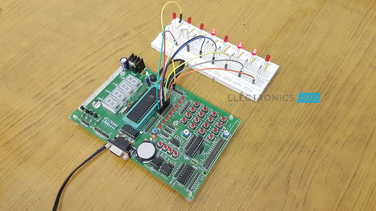
LED blinking is the most basic project with a micro-controller to see a physical output. One can understand the concept of input-output configurations of the general-purpose I/O port in a micro-controller with the simple LED blinking project. The LED`s are simple electronic display units available. This tutorial will explain the method of interfacing LED with 8051 micro-controllers and to develop a c code for blinking the same.
The AT89C51 micro-controller has 4 general purposes I/O ports which can be configured as input or output. Configuring the port pins as output, the state of the port pins can be controlled in firmware either high or low. When the port is configured as input, reading the pins will read the voltage state of the pins.We need to configure the port pins as output for a led blinking process.
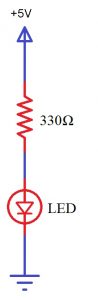
Interfacing LED with Micro-controller Pin

The above image is the simple way of interfacing an LED with a micro-controller. The anode is connected to the micro-controller and cathode is connected to ground through a resistor. When the voltage at the controller pin is high the LED will be turned ON and when the voltage is low the LED will be turned off.
Components Required
- AT-89C51 (8051 Micro-controller)
- 8 LED`s
- 8 Resistors – 1 KΩ
- Crystal oscillator – 11.0592 MHz
- 2 Capacitors – 33 pF
- 2 Resistors – 10 KΩ
- 1 Capacitor – 10μF
- 1 Push Button
- 8051 Programmer
- 5V Power Supply
Circuit Design
The circuit mainly consists of AT89C51 micro-controller. AT89C51 belongs to the family of 8051 micro-controller. It is an 8-bit micro-controller. This micro-controller has 4KB of Flash Programmable and Erasable Read Only Memory and 128 bytes of RAM. This can be programmed and erased a maximum of 1000 times.
It has two 16 bit timers/counters. It supports USART communication protocol. It has 40 pins. There are four ports are designated as P0, P1, P2, and P3. Port P0 will not have internal pull- ups, while the other ports have internal pull-ups.

In this circuit, LEDs are connected to the port P0. The controller is connected with external crystal oscillator to pin 18 and 19 pins. Crystal pins are connected to the ground through capacitors of 33pf.
Voltage drop across LED
Light Emitting Diodes are the semi conductor light sources. Commonly used LEDs will have a cut-off voltage of 1.7V and current of 10mA. When an LED is applied with its required voltage and current it glows with full intensity.
The Light Emitting Diode is similar to the normal PN diode but it emits energy in the form of light. The color of light depends on the band gap of the semiconductor. The following figure shows “how an LED glows?”
Thus, LED is connected to the AT89C51 microcontroller with the help of a current limiting resistor. The value of this resistor is calculated using the following formula.
R= (V-1.7)/10mA, where V is the input voltage.
Generally, microcontrollers output a maximum voltage of 5V. Thus, the value of resistor calculated for this is 330 Ohms. This resistor can be connected to either the cathode or the anode of the LED.
Algorithm
- Initially, include the “reg51.h” header file in your code.
- Now write a function for producing delay using for loop.
- Start the main function.
- Inside the while loop write the condition to port pin for making it logic high or low.
- Initially, make it high for some delay of 1000 microseconds.
- Now make the port pin low.
- Again give some delay of 1000 microseconds.
- Repeat this for 8 times using for loop.
- In another loop, try to represent the binary equivalent of the first 255 number using LEDs.
- Now close the while loop and also main.
Code
#include<reg51.h>
sfr p0=0x80;
void delay(int a);
void main(void)
{
//p0=0x00; // p0 declare as a output port
while(1)
{
p0=0x00;
delay(500); //delay generation for 500 ms
p0=0xff;
delay(1000); //delay generation for 1 second
}
}
// Delay generation of 1 Ms
void delay(int a)
{
int i,j;
for(i=0;i=1075;i++)
{
}
}

Comments
Post a Comment