7Segment Interfacing with 8051
7-Segment Interfacing with 8051
Seven segment displays (SSD) are used to indicate numerical information. Seven segments display can display digits from 0 to 9 and even we can display few characters like A, b, C, H, E, e, F, etc. These are very popular and have many more applications. So, in this project, We’ll show you how to interface 7 Segment Display (SSD) to 8051 Micro-controller.
This article describes you how to interface seven segment display to AT89C51 micro-controller. This system displays the digits from 0 to 9 continuously with a predefined delay. In the process, I’ll design two circuits: one circuit with a single digit 7 Segment Display and the other circuit consists of a 4-digit 7 Segment Display.
Circuit Principle
Seven segment displays internally consist of 8 LED`s. In those LED`s, 7 are used to indicate the digits 0 to 9 and single LED is used for indicating decimal point. Generally seven segments are two types, one is common cathode and the other is common anode.
In common cathode, all the cathodes of LED`s are tied together and labeled as com. and the anode are left alone. In common anode, seven segment display all the anodes are tied together and cathodes are left freely. Below figure shows the internal connections of seven segment Display.
In the first circuit, I will interface a Common Cathode Single Digit 7 Segment Display to the 8051 Micro-controller while in the second circuit, I will interface a Common Anode type 4-Digit 7-Segment Display to the 8051 Micro-controller.
Circuit Diagram

Circuit Components
- AT89C51 Micro-controller
- AT89C51 Programming board
- Programming cable
- 12V DC battery or adapter
- Common Cathode 7 segment Display
- Common Anode
Circuit Design
Circuit 1
Here, common cathode seven segment is used to display the digits. In this circuit, pins a to h of the 7 segment are connected to the PORT 2 of the micro-controller and com pin is connected to the ground through the 330 ohm resistor. This resistor is used to drop the voltage. Since we are using common cathode seven segment we need to send LOGIC 1 to the segments to glow.Figure shows structure of common cathode seven segments. Here dot is used for indicating the decimal point. Here all the cathodes of LED’s are connected to the Gnd pin. The operating voltage of this LED’s is 2 to 3V but from controller we will get 5V so to drop the remaining voltage we have to connect a to g pins to the controller through the resistor.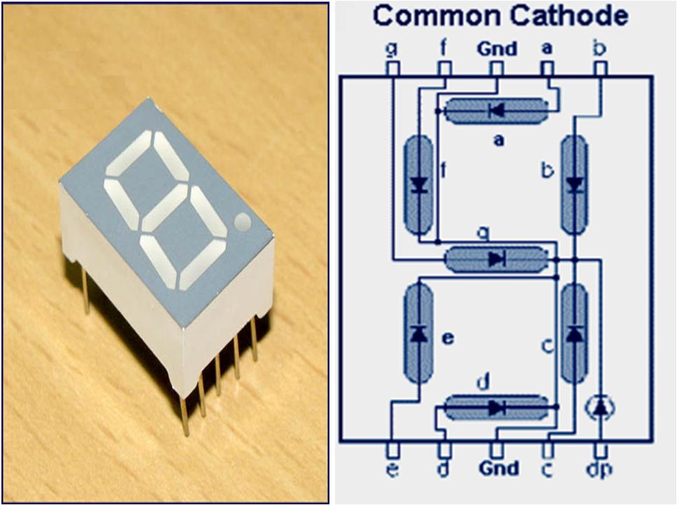
Common cathode 7 segment DisplayCircuit 2
Since the 4-digit 7-Segment display used in the second circuit is of common anode type, we need to drive the LED segments through the common terminals. I have used 4 NPN Transistors to drive the 4 common anodes and the transistors are controlled by the 8051.Coming to the segments a to h, they are connected to PORT-0 Pins of 8051.Digit Drive Pattern
To display the digits on 7 segment, we need to glow different logic combinations of segments. For example if you want to display the digit 3 on seven segment then you need to glow the segments a, b, c, d and g. The below table show you the Hex decimal values what we need to send from PORT-2 to Display the digits from 0 to 9.DIGIT DP G F E D C B A HEX VALUE 0 0 0 1 1 1 1 1 1 0x3f 1 0 0 0 0 0 1 1 0 0x06 2 0 1 0 1 1 0 1 1 0x5b 3 0 1 0 0 1 1 1 1 0x4f 4 0 1 1 0 0 1 1 0 0x66 5 0 1 1 0 1 1 0 1 0x6d 6 0 1 1 1 1 1 0 1 0x7d 7 0 0 0 0 0 1 1 1 0x07 8 0 1 1 1 1 1 1 1 0x7f 9 0 1 1 0 0 1 1 1 0x67 NOTE: These values are suitable only for a Common Cathode display. If you want to drive a Common Anode display, then you have to take the complement of each bit and replace the hexadecimal values in the code (which I have done in the code of the second circuit).4-Digit 7-Segment Display- Resistors – 10KΩ X 2, 330Ω, 1KΩ X 8, 470Ω X 4
- 1KΩ X 8 Resistor Pack
- 33pF Ceramic capacitors x 2
- 11.0592 MHz crystal
- 10μF Electrolytic capacitor
- 2N2222 NPN Transistor X 4
- Push button
- Connecting wires
Algorithm
For Circuit 1
- First initialize all the segment hex values of the digits in an array.
unsigned char arr[10]={0x3f,0x06,0x5b,0x4f,0x66,0x6d,0x7d,0x07,0x7f,0x67};
- Now take for loop and assign array values to the PORT2 with some time delay.
for (i=0;i<10;i++)
{
P2=arr[i];
delay_ms(500);
}
For Circuit 2
- First initialize all the segment hex values of the digits in an array.
unsigned char ch[]={0xc0,0xf9,0xa4,0xb0,0x99,0x92,0x82,0xf8,0x80,0x90}
2. As per the value, switch the digits.
void display (unsigned long int n)
{
led=ch[n/1000];
sw1=1;
sdelay(30);
sw1=0;
led=ch[(n/100)%10];
sw2=1;
sdelay(30);
sw2=0;
led=ch[(n/10)%10];
sw3=1;
sdelay(30);
sw3=0;
led=ch[n%10];
sw4=1;
sdelay(30);
sw4=0;
}

Comments
Post a Comment